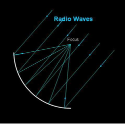
A parabolic antenna brings radio waves from a particular direction in space (along the axis of the parabola) to a focus as in Figure 1. The radio waves from the direction along the axis arrive at the focus “in phase,” i.e., they have all traveled exactly the same distance. The radio waves are collected at the focus by a “feed” antenna where they are converted to electrical signals and amplified. These signals are then sent to other electronics for further processing.
A dish antenna is most sensitive to radio waves from a narrow range of directions near its axis. This angular region of sensitivity, corresponding to a small spot on the sky, is called the antenna’s beam. The width of the beam depends on the diameter of the antenna and the wavelength of the radio waves observed. The beam width (in radians) is roughly the wavelength of the radio wave divided by the diameter of the antenna. For example, a 100 meter antenna observing at a wavelength of 21 centimeters (a frequency of 1420 MHz) has a beam width of 0.0025 radians or 0.14 degrees (about one third the angular size of the Moon).
The ATA is an array of many small dishes that can be combined to form the equivalent of a single large dish antenna. How this works is illustrated in the following diagrams based on originals by Dr. Ron Ekers.
We can replace the solid surface of a large dish by a set of small dishes positioned along the parabolic surface as in Figure 2. Each small dish brings radio waves to a focus and converts them to electrical signals. These signals then travel by cables to the focus of the large dish. This replicates the effect of the large single dish. The cables simply replicate the path that the reflected radio waves would have taken in Figure 1.
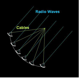
figure 2
But there is no reason to send the cables up to the original focus position. As long as the lengths of the cables remain the same, they can instead go down to the ground and be collected by electronics there, as in Figure 3.
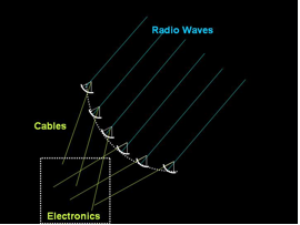
figure 3
There is also no reason to suspend the small dishes above the ground. As long as we know where they would have been on the surface of the original large dish, we can put them on the ground and add an appropriate amount of cable to delay the signals as shown in Figure 4. The dish that is closest to the original position (the dotted line) will need the most delay. Combining the signals collected by the individual dishes with the appropriate delays synthesizes the effect of the large single dish, resulting in a synthesized beam equivalent to that of the large dish.
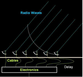
figure 4
This arrangement of small dishes is called a phased array since the cables and electronics ensure that the radio waves from a particular direction are “in phase.” By carefully changing the lengths of the cables and tweaking the electronics, we could bring radio waves from a different direction into phase. In other words, we could steer the phased array without moving the dishes. If we replicate the electronics and cables, we can point in two directions at the same time as shown in Figure 5.
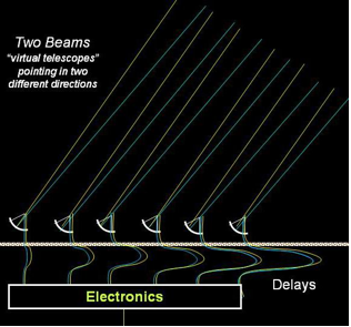
figure 5
In practice, we use one set of cables with separate sets of electronics to change the relative delays between the dishes, and thereby synthesize multiple beams. The synthesized beams may be steered anywhere on the sky, but we usually limit them to an area corresponding to the beam width of an individual dish. (The sensitivity of the synthesized beam decreases dramatically outside of this area.) This area is called the field of view (FOV) of the array. For the ATA, with 6.1 meter dishes, the FOV at a wavelength of 21 cm is 0.04 radians or 2.5 degrees (five times the angular width of the Moon).
SETI observations use three beams to observe three stars (or positions on a sky survey grid) at the same frequency at the same time in order to eliminate signals caused by terrestrial interference. If a signal appears in two or more beams, it is almost certainly from our own equipment or from manmade interference. If a signal appears in only one beam, it is worthy of further scrutiny.
